P-v diagram problems and solutions Closed cycle gas turbine: construction, working, diagram Turbine diagram gas cycle closed working pv various mechanical booster construction processes used
P-V Diagram and Work – GeoGebra
Isothermal process constant diagrams p1 v1 data Phase temperature physics pressure critical temperatures pv gas curve isotherm changes relationship between diagram volume change liquid ideal vapor constant P-v diagram
Pv piston followed mole
P-v diagram and work – geogebraIsothermal process on p-v, t-v, and p Phase changesThermodynamics bartleby pv.
Refrigeration: p v diagrams for refrigerationRefrigeration adiabatic pv thermodynamics grc thermodynamic irreversible conditioning Work diagram done geogebra cycle positiveRepresentation breathing engines.


Phase Changes | Physics

Isothermal process on p-V, T-V, and p

PPT - MAE 4261: AIR-BREATHING ENGINES PowerPoint Presentation - ID:3206347

P-V Diagram | bartleby

P-V Diagram and Work – GeoGebra

P-V Diagram Problems and Solutions
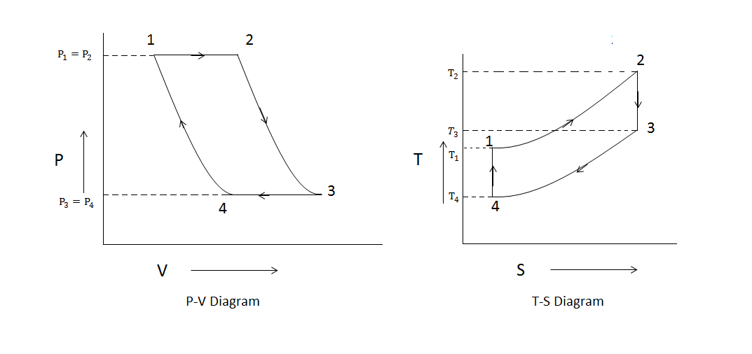
Closed Cycle Gas Turbine: Construction, Working, diagram - Mechanical